FreeCore
Library
.MIF File Generator Utility
by
Rune Baeverrud
| August 19, 1997: | Version 1.2: | Added SNR calculation | |
| August 18, 1997: | Version 1.01: | Options section added, 'Include End Angle' and 'Symmetry' |
A .MIF (Memory Initialization File) file is used to preload the EAB's in Altera's FLEX devices, like the Altera FLEX 10K family. When you instantiate a ROM or RAM in a schematic or an AHDL file, you have the option to specify a .MIF file for preloading the EAB with some default data.
You may use the EAB's as look-up tables. For instance, you could use the EAB's for storing digital waveforms. A typical digital waveform is the digital representation of a sine or cosine waveform.
The MIFGEN utility will generate .MIF files for you with sine or cosine digital waveforms. You have the option to specify several parameters, like amplitude, offset, angle range and so on. The MIFGEN utility is a stand-alone 32-bit executable running under Windows NT or Windows 95.
 |
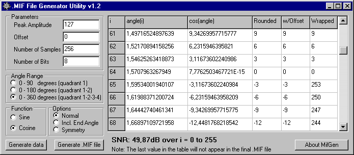
Here is a sample output of the MIFGEN utility, using the above parameters:
-- Memory Initialization File
-- Generated by .MIF File Generator Utility v1.2
-- by Rune Baeverrud

-- Angle Range 0-360 degrees (quadrant 1-2-3-4)
-- Function type    : Cosine
-- Options          : Normal
-- Peak Amplitude   : 127,00
-- Offset           : 0
-- Number of Samples: 256
-- SNR:             : SNR: 49,87dB over i = 0 to 255

DEPTH = 256;
WIDTH = 8;

ADDRESS_RADIX = DEC;
DATA_RADIX = DEC;

CONTENT
  BEGIN
    0 : 127;
    1 : 127;
    2 : 127;
    3 : 127;
    4 : 126;
    5 : 126;
    ...
    ... (some lines removed here)
    ...
    250 : 126;
    251 : 126;
    252 : 126;
    253 : 127;
    254 : 127;
    255 : 127;
END; |
| Parameter Name | Description/Explanation |
| Peak Amplitude | A sine or cosine (with no weigth) has a value in the range [-1,1]. The sine or cosine generated will be multiplied by the Peak Amplitude to generate an intermediate floating point representation of the waveform in the range [-Peak Amplitude, Peak Amplitude]. This value can be viewed in the 3rd column of the table ("cos(i)" or "sin(i)"). The floating point value is then rounded or quantized to the nearest whole integer - this is in the 4th column of the table ("Rounded"). |
| Offset | The Offset value is then added to Rounded, and the result can be viewed in the 5th column of the table ("w/Offset"). |
| Number of Samples | The Number of Samples parameter gives the number of entries in the .MIF file. In the on-screen table, the number of samples is actually one more, so that a complete quadrant, half or circle can be more easily verified. |
| Number of Bits | The Number of Bits parameter is used for two purposes. First, the WIDTH parameter has to be specified in the .MIF file. Second, if the "w/Offset" column contains negative values, the waveform is assumed to be bipolar and it will be represented in 2's complement. Since the .MIF file itself does not accept negative values, the number -3 is converted to 2^(Number of Bits) - 3. Assuming Number of Bits is 8, the new value will be 2^8 - 3 = 256 - 3 = 253. This is the value appearing in the last column, which is also the value written to the .MIF file. |
| Angle Range | The Angle Range parameter specifies the angle range of which the Number of Samples will be applied. The angle range is evenly divided by Number of Samples from 0 degrees up to 90, 180 or 360 degrees. |
| Function | Function specifies if you want to generate a sine or cosine within the angle range. |
| Options | Options lets you specify one of the following options, which
apply to the angle range:
|
When you have entered your parameters, press the Generate Data button and the on-screen table will be filled with the appropriate values for your inspection. There is also an SNR (Signal-to-Noise Ratio) readout, based on the Signal Power / Quantization Noise Power. If you are satisfied with the result, press the Generate .MIF File button to create the .MIF file itself. You will be asked to supply a name for the new file.
| Download MIFGEN.ZIP |
![]()
Last updated 08 Feb 2001 12:22